BASIC EARTHING - Electrode Resistance

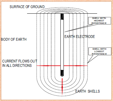
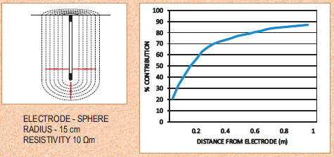
RESISTANCE AREA OF AN EARTH ELECTRODE
The resistance of earth surrounding a vertical electrode is dependant mainly upon the type of soil surrounding the electrode.

This can be visualised as cylindrical shells of earth of equal thickness. Assuming that the soil is of uniform resistivity, the greatest resistance is the shell immediately surrounding the electrode which has the smallest cross section of soil at right angles to the flow of current through the soil. Each succeeding shell has increased cross section and therefore lower resistance. At a distance of say 3m from the rod, the area of the path is so large that resistance of successive shells is almost negligible compared to that of the shell immediately surrounding the rod.

The resistance varies inversely at the cross section and, within 50- 60cm from the electrode where the conducting path is small, the resistivity of the soil is an important factor. Measurements show that about 90% of total electrical resistance surrounding an electrode is generally within a radius of 1.8 to3mm from the electrode. The same theory applies to an electrode laid horizontally in the ground, although the perfect cylindrical dissipation is lost due to the proximity of the electrode to the surface.


Earth Rod Installation Distances Specification:
Earth rods shall be installed:"AT A DISTANCEOFNOCLOSER THANTHEIR LENGTH"


EARTH ROD ELECTRODE RESISTANCE

Resistance Contribution vs Distance
Around an earth electrode the resistance of the soil is the sum of series resistances of vitual shells of earth probagating outward from the
electrode. Shells nearest to the electrode have the smallest surface area and hence the largest resistance.

The figure illustrates the contribution of the earth to the total resistance of
the electrode at increasing distances from the surface of the electrode.

As can be established from the figure, 67% of the total resistance is accounted for at a distance of 0.3m from the electrode. In high resistivity locations, decreasing the resistivity in the area close to the electrode by use of conductive earthing compound (E-Mix) will improve the effectiveness of the earth system.

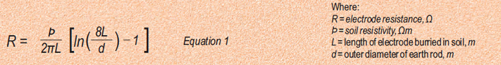
SINGLE EARTHROD ELECTRODE - ELECTRODE RESISTANCE
The resistance of a single earth rod is calculated if the soil resistivity is known. An electrode driven vertically, the electrode resistance can be calculated using the equation:


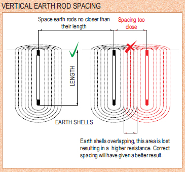
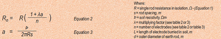
MULTIPLE EARTHROD ELECTRODE-ELECTRODE RESISTANCE
The combined resistance of rod electrodes in parallel can be obtained from the following equation:


The above equations assume that the rod electrodes can be represented approximately by hemispherical electrodes, having the same earth resistance. This assumption is satisfactory provided that the 
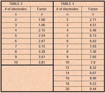
spacing between the rods is less than their length.
For electrodes equally spaced around a hollow square, e.g. around the perimeter of a building, use λ fromTable 3.
For three rods placed in an equilateral triangle, or in a Lformation, use λ = 1.66.
Table 3 may also be used for electrodes arranged in a rectangle, where n is given by (total number of electrodes/4)+1. Provided that the length to width ratio of the rectangle does not exceed 2, the error will be less than -
6%.

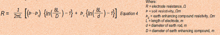
EARTH ROD ELECTRODE RESISTANCE USING E-MIX CONDUCTIVE EARTHING COMPOUND

E-Mix conductive earthing compound, is a technique where the ground immediately surrounding an earth electrode is replaced with a low
resistance material. The intent is to reduce the earth electrode resistivity. Use of E-Mix would be in areas where the soil resistivity is very high and problems arise in trying to achieve the require electrode resistance.

SINGLE EARTHROD ELECTRODE-ELECTRODE RESISTANCE
The resistance of a single earth rod is calculated if the soil resistivity is known. An electrode driven vertically, the electrode resistance can be calculated using the equation:


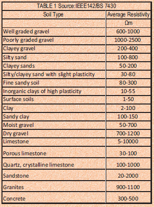
RESISTIVITY OF SOILS
The resistivity of soils varies from site to site and is influenced by:
- the depth from the surface
-the type and concentration of soluble chemicals in the soil
-the moisture content
-the soil temperature
The soil resistivity is dependent on the electrolyte in the soil. The presence of surface water does not necessarily indicate low resistivity.
In the absence of a proper soil survey.
Table 1 gives typical soil types and the expected resistivity.

REFERENCES
1. IEEE 142
2. BS 7430
3.V. PANGONILO


- Top of page -


Tel No.: +27 (0)11 786-4818
Fax No.: +27 (0)11 786-4819
Email: info@lectro-tech.co.za
Address: 712 - 6th Street, Wynberg, Gauteng, South Africa
Terms & Conditions
  © Copyright Lectrotech
 
 
Responsive Web Design & Online Marketing - www.itdev.co.za