THEORY
In the fall of potential test, three points of earth contact are considered:
1. The earthing system under test (X)
2. A current probe (Z) placed some distance from the earth system under test.
3. A voltage probe (Y) that is inserted at various distances between the system under test and the current probe.
Ideally the X-Z distance should be 10 times the earth rod length or grid width (i.e. 3m rod, 30 m spacing).
With this method of test, the meter injects a current into the earth system under test (X). The current flows through the earth to the
remote current probe (Z) and returns to the meter. As the current flows through the resistive material (earth) a voltage drop is created.
This voltage drop is proportional to the amount of current flow and the resistance of the earth system to earth. The voltage probe (Y) is
used to measure this voltage drop. The meter then knows both the amount of current flow and the resulting voltage drop. It simply uses
Ohm’s law to calculate and display the resistance.
The resistance is measured at several locations moving the voltage probe (Y) at regular intervals, each of them equal 10% distance XZ.
The resistance measurements are then plotted along with the distance between the earth system and the Y probe. From this graph the
actual earth system resistance can be determined along with the validity of the test.
The earthing system must be electrically isolated, if not isolated, the readings will reflect all the earthing systems in the area hooked in
parallel. The reading will always be very low and have no bearing on the actual earth system resistance. The result is not an inaccurate
test, but an invalid one.
Many factors can affect the test thus, it is strongly recommended to perform the test in at least two perpendicular directions. If
enough space is available for additional testing, more measurements will increase the accuracy of the soil model and will help eliminate
the errors caused by nearby buried conductors, pipes or other metallic parts.
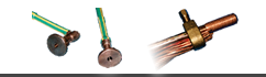
EQUIPMENT
A 4-Pole or a 3-Pole Digital - Earth Resistance Tester | At least three probes
Insulated wire leads | Tape measure
Hammer (to secure probes into earth)
SAFETY WARNING INFORMATION
There is a possibility that a fault on a power system will cause a current flow on the ground system while a test is in progress, causing
unexpected high voltages on the current and voltage probes. If a significant risk exists, it is recommended that the persons performing the
test use protective rubber gloves and a rubber safety mat during the test.
Note: The earthing system must be electrically isolated during this test. This should only be performed by qualified personnel
and after permission is granted by all responsible personnel. Check for current on the earth before disconnecting. Do not disconnect the earth of a live circuit. Disconnecting the earth
of a live circuit could cause severe injury or even death.
PROCEDURES
Note 1: In order for the test to provide valid results, the earth system must be de-energized and disconnected from the utility neutral
system.
Any connections that could provide a path to the utility neutral must be disconnected.
Note 2: Check your operator’s manual for detailed meter operation.
1) Isolate the earthing grid under test from all other supplemental grounds (i.e. water pipes, building steel, etc.).
Also disconnect any neutral connections and all telcom.
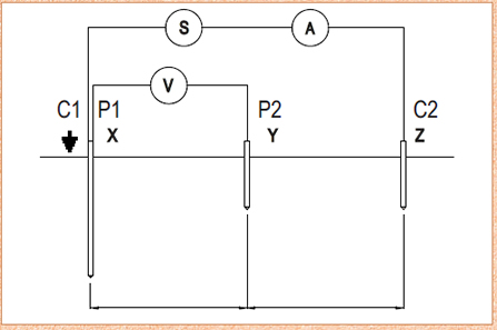
2) If a 4-pole earth resistance meter is used, some meters require a connection between the C1 and P1 terminals. If a 3-pole earth
resistance meter is used, no connection between the terminals is required.
3) Connect the C1 connection to the earth rod or system to be tested.
4) Install the current probe (Z) and the voltage probe (Y) in accordance with the table.
The (Y) probe must be in line with the earth and the (Z) probe. Connect the probe to the P2 connection on the meter.
4.1 equal to 5-10 times the length of the earth rod
Useful table for probe spacing:
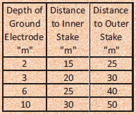
4.2 5-10 times the diagonal distance of the earth grid under test
4.3 when a ring or grid is being tested, the distance must be measured from the outer edge of the ring.
The probe must have good contact with the earth. Connect this probe to the C2 connection on the meter.
5) Push button to activate the meter. When a measurement is shown, allow the reading to stabilize and record the reading in the chart
on p62.
6) Move the (Y) probe to 10% of the distance between earth system and (Z). Test as in step 5 and record the results in a chart
as on p62. Repeat this step (moving the probe at 10% intervals) until the 90% distance is reached.
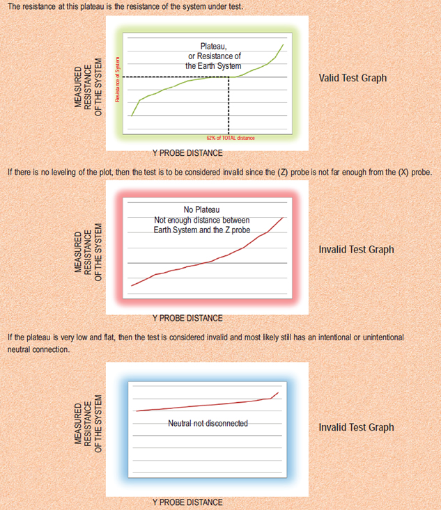
7) Once all the readings have been recorded, plot a graph with the measured resistances as the y-axis. The distance from the (X)
probe is the x-axis. At approximately 62% of the total distance, a plateau or “flat spot” in the plot.
The resistance at this plateau is the resistance of the system under test. If there is no leveling of the plot, then the test is to be
considered invalid since the (Z) probe is not far enough from the (X) probe. If the plateau is very low and flat, then the test is
considered invalid and most likle y still has an intentional or unintentional neutral connection.
8) If difficulty is encountered in obtaining readings, it is most likely caused by a high probe to earth resistance. Pouring water on
the probes sometimes helps. This will not have any significant effect on the reading.
9) If available installing longer probes that provide a more surface contact may also help. Some meters have less difficulty
overcoming the probe to earth resistance than others.
10) Perform additional testing in at least one perpendicular direction. The readings should be averaged.
REFERENCES
1. A simple guide to earth testing : Megger